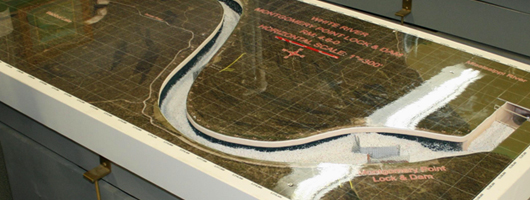
HSR Model
Hydraulic Sediment Response (HSR) modeling is small scale, physical sediment transport modeling. Using this technology, river engineers are able to replicate the mechanics of an actual river or stream on an area the size of a normal table top.
Physical Model Setup Overview
The HSR model consists of a planform insert constructed from polyurethane foam fabricated to geo-referenced aerial photography. The insert is placed within a hydraulic flume that contains a reservoir, electronic control valves, pumps, a constant head pipe network, and flow meters, all interfaced with a computerized control system.
Discharge and sediment (granular plastic, urea, specific gravity 1.4) are simulated through the insert channel. A model coordinate system is established to collect all data. Lasers are used to collect detailed bathymetry and normalized velocity distribution from the model for comparison to hydrographic surveys and Acoustic Doppler Current Profiles (ADCP) from the river. High definition cameras are also used for flow visualization and general model observation recording.

Figure 2:Interfaced with a computerized control system
- Table Top Size
- Three Dimensional Bed Response
- Flow Visualization of Surface Velocity Trends
- Every Part of the Model is Visible, Dynamic and in Real Time
- Relatively Inexpensive
- Results Usually Obtained Within a Few Months
Problems that can be addressed by an HSR model
- Excessive dredging (removing sediment buildup from shallow sections of the river
- Restricted channel widths
- Dangerous bends Side channel modifications
- Channel realignments
- Harbor shoaling
- Pier scour
- Variety of other sediment related problems
Model Calibration and Replication
The HSR modeling methodology employed a calibration process designed to replicate the conditions in the river at the time of the model study. Replication of the model was achieved during calibration and involved a three step process.
First, planform "fixed" boundary conditions of the study reach, i.e. banklines, islands, side channels, tributaries and other features were established according to the 2010 high resolution aerial photography. Various other fixed boundaries were also introduced into the model including any channel improvement structures, underwater rock, clay and other non-mobile boundaries.
Second, "loose" boundary conditions of the model were developed. Bed material was introduced into the channel throughout the model to an approximate level plane. The combination of the fixed and loose boundaries served as the starting condition of the model.
Third, steady state discharge simulation tests were run through the model. Adjustment of the discharge, sediment volume, model slope, fixed boundaries, and entrance conditions were refined during these tests as part of calibration. The mobile bed developed from a static, flat, arbitrary bed into a fully-formed, dynamic, and three dimensional bed responses. The resulting bed configuration was surveyed numerous times during the calibration tests and compared to recent river bathymetry. Repeated tests were simulated for the assurance of model stability and repeatability. When the general trends of the model bed bathymetry were similar to observed recent river bathymetry, and the tests were repeatable, the model was considered replicated and alternative testing then began.


