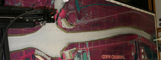
Planform Inserts
1. Foam Board
Two sheets of foam board must be ordered in advance of model insert construction, a 3"x4'x8' or 10' 18 pcf NC proof board light and a 1"x4'x8' or 10' 30 pcf NC proof board light.
2. Georeferenced Image
The Corps of Engineers provide a printed georeferenced image. The image and PVC sheet are then fastened to the top of the 18 pcf NC proof board light. The image of the area is obtained from an engineer or engineering technician using georeferenced aerial photographs in .tif format and then adding (as reference files) various features such as the state plane coordinates, north arrow, and exiting dikes and weirs. The river, dikes and weir miles are marked. Various features can be called out such as county names, island and structures.
3. Laminated
Once the overview layout is completed to the engineers satisfaction the file is converted to a PDF format and copied to a flash drive which is taken to a private printing contractor to print at a chosen scale. The printout is then laminated and glued to a 4'x 8' or 10', 1/4" PVC sheet. The next step is to trim the PVC to the same dimension as the overview image. The PVC used is of the softer type, which can be cut with a razor craft knife.
4. Simple Jigsaw
Now the 1 inch foam baseboard and the 3 inch foam board are cut to the specified dimensions of the overview image. A simple jigsaw is used to accomplish this.
5. Prepare the Baseboard
The next step is to epoxy the 1 inch baseboard to the 3 inch foam board card using a bond 101 epoxy. It takes two bottles of this spread out evenly on the 1 inch baseboard. Then a 3 inch foam board is placed on top of this and weighted down with 25 pound weights that are evenly distributed over the entire surface in order to eliminate uneven settlement of insert layers and glue. Also when performing this task care must be taken so that insert layers remain aligned. Corrections during this process may be necessary. Once weighted down and any shifting is corrected, the layers must be left to cure for 48 plus hours.
6. Epoxy Baseboard
The next step is to epoxy the 1 inch baseboard to the 3 inch foam board card using a bond 101 epoxy. it takes two bottles of this spread out evenly on the 1 inch baseboard. Then a 3 inch foam board is placed on top of this and weighted down with 25 pound weights evenly distributed over the entire surface to eliminate uneven settlement of insert layers and glue. Also when performing this task care must be taken so that insert layers remain aligned. Corrections during this process may be necessary. Once weighted down and any shifting is corrected, the layers must be left to cure for 48 plus hours.
7. Cut
When all glue and caulk material has cured completely, the main channel and side channels of the river or stream being modeled are cut out with a Jig Saw. Cuts are made along the river bank vegetation lines. Beginning on the downstream end, using a fine tooth blade that has been cut to no more than 3 inch in length, the river channels are then cut out. The cut should end approximately 1/2 inch from the upstream end of the insert. This small section at the upstream end of the river channel should be left in place to contain flow within the model insert channel. A chisel (or chisels of varying sizes) is then used to cut the channel down to the depth of the 1 inch base board, again leaving approximately 1/2 inch at the end of the entrance as a wall.
8. Touchup
Next, slots for the Dikes are cut using a Dremel. These slots are to be cut in line with the dike angle, and also they are to be cut through the entire 3 inch foam layer but not the 1/4 inch PVC layer. The metal cutting disk is well suited for this task. Larger, 1/4 inch wide, slots on each river bank are cut from the channel bottom through the top of the PVC layer, approximately 1/2 inch from the downstream end of the insert. This larger slot will be used for an exit gate to be raised and lowered during model operation. The final step is to silicone the joint where the cut out channel wall meets the foam channel floor, along with any other imperfections in the foam. After the silicone caulk has cured, then the entire channel is to be painted with Black rubber swimming pool paint as a final seal of the foam.
9. Finish
Grayish, white urea sediment (specific gravity ~ 1.4) and water are added to the finished model, which depicts the natural body of water flowing.


